
Maximize Market Research has published a detailed sheet metal fabrication industry report.
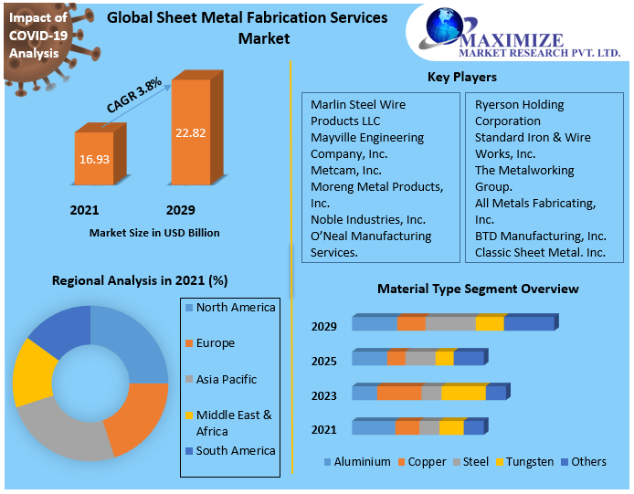
According to the report, the global sheet metal fabrication services market was valued at $16.93 billion in 2021. It will reach nearly 22.82 billion in 2029 with a CAGR of 3.8% growth rate.
What Is Sheet Metal Fabrication?
Sheet metal fabrication is the process of turning flat metal sheets into metal structures or products for personal and industrial usage. The process typically involves cutting, punching, folding, welding, and surface treatment-like activities.
The metals used in the process are aluminum, copper, steel, tungsten, brass, tin, platinum, gold, and silver. The process forms sheets of a variety of thicknesses, ranging from leaf or foil to plate. However, the construction industry uses steel and aluminum metals the most to develop metal sheet frames for various applications, including door and window frames, enclosure, ducts, and panels.
What Are the Challenges Solved by 3D CAD Modeling & Design Services for Sheet Metal Products?
For years, the sheet metal fabrication industry has faced many challenges depending on 2D shop drawings. With the emergence of sophisticated 3D CAD design & modeling services, these challenges have their answers. Let’s take a brief review of those challenges.
Material & Bending Constraints:
We know metal grows when you bend it. However, the growth or expansion of metal depends mainly on the types of metal. Engineers or designers cannot precisely count metal expansion factors. It led to several critical errors and proved costly due to rework and material wastage.
To avert material-related bending constraints, modern 3D CAD shop drawing software uses built-in tables to accurately calculate and foreshorten the flats and optimize the bending process, which eventually saves time and material waste.
Alignment & Assembly Issues:
Flange orientations, thickness variations, and tricky geometry are known challenges when a 2D designer wants to convey a design precisely. By adopting a top-down approach, sheet metal components have complex bends, curves, and interlocking features when designing various sheet metal parts, including bends, flanges, and cutouts.
Let me clarify what is a top-down approach first. The top-down approach involves the creation of the main framework first and related allied components using a parametric approach. It helps designers make quick changes in the main framework and will reflect automatically in components.
3D CAD drawings help designers visualize the alignment and assembly issues upfront by flagging real-time conflict alerts and tips.
Gaps & Complex Corners:
Gaps, holes, excessive welding, and endless grinding are common issues when designers miss the folded geometry of tiny spots in the sheet metal fabrication design process. They may cost fabricators many valuable hours and waste materials.
3D sheet metal modeling provides animations to join various assemblies and tricky parts together. So everyone on the team can visualize the errors and conflicts left in design gaps and complex corners. The software provides a miter flange command to trace complex miters in sheet metal design.
CNC Fabrication Mistakes:
We must convert the sheet metal design into CNC-compatible (.DXF) files to proceed with the CNC fabrication process. The manual conversion process from 2D shop drawings may prove error-prone. However, modern, sophisticated 3D CAD software accomplishes the conversion process automatically with desired precision or accuracy. Thus, CNC files capture every bend, notch, and detail beautifully to minimize errors in fabrication using CNC machines.
Tired of Design Inaccuracies in Sheet Metal Projects?
Our 3D CAD modeling services help eliminate costly rework and streamline fabrication. Get models that perfectly match your production goals.
Key Features of Sheet Metal Modeling in 3D CAD Modeling Software
At Shalin Designs, we recommend using 3D modeling for making sheet metal products due to the compelling features available in 3D CAD design software.
Flange Creation:
- Technically, the flange is formed by bending sheet metal along a straight line.
- The software provides a flange creation tool/feature. The designer selects edges or sketching lines to define the bend lines.
- The software automatically generates a flange bend based on specified parameters in the module.
- The parameters include length, angle, and orientation.
Calculations for Bend Allowance:
- When extra material is needed to accommodate the bending process, the calculations for required additional material are called bend allowance.
- 3D CAD modeling software automatically calculates bend allowance based on factors such as types of material, bend thickness, and bend radius.
Folding & Unfolding Feature:
- 3D sheet metal modeling software allows users to transform a 3D sheet metal model into a 2D flat design. So, users can print and use templates for cutting and bending during the production phase.
- Similarly, designers can fold a flat design back into 3D form to visualize the final products.
Corner Relief & Fillet:
- Corner relief and filet features in 3D CAD drafting software help designers avoid creating sharp edges.
- Sharp edges are hazardous and lead to material stress concentrations.
- A designer will have options, including specifying the corner relief and filet’s type, size, and shape.
Hole & Cutout Creation:
- The software allows the designer to add holes and cutouts to the sheet metal components.
- Users can specify hole diameter, location, type, and other parameters.
- Inputs are essential to accommodate fasteners, connections, etc.
Flattening Analysis:
- Flattening analysis in 3D modeling software is essential to compute how accurately a 3D sheet metal model is unfolded into a 2D flat design.
- Thus, it ensures that the flat design successfully maintains the correct dimensions and shapes for fabrication.
Material Library:
- It provides a database of predefined material and its properties.
- The properties include yield strength, elasticity, and thermal conductivity.
- It aids in accurately simulating material behavior during the sheet metal fabrication forming process.
Gauge & Thickness:
- The software allows defining & modification in gauge and thickness of the sheet metals.
- It helps in accommodating various manufacturing needs and material specifications.
Tab & Corner Management:
- The tab is a small extension of sheet metal parts.
- The tab provides structural support or facilitates assembly.
- The corner management tools aid in the creation & modification of corners.
- Corners help in achieving the desired shape and structural integrity.
Bend Order & Sequence Control:
- The software allows the designer to specify the order in which bends are made.
- Maintaining bend order ensures bends don’t interfere with each other and achieve shapes accurately.
Automatic Bend Deduction:
- It determines the flat pattern dimensions essential to achieve the expected final shape after bending.
- The tool automatically calculates bend deductions based on specified metrics.
Parametric Design:
- It allows the development of models where changes in any property parameter of any component can reflect automatically across the entire model in all parts.
- It offers flexibility in design iterations and consistency.
Design Validation & Simulation:
- The software can simulate various conditions, such as stress, thermal or dynamic analysis, etc.
- It ensures that the design meets performance criteria and withstands real-world conditions.
Bend Table Customization:
- The Bend table defines bending parameters for different materials or processes.
- The software enables users to customize bend tables to match their unique manufacturing requirements.
- It provides greater control over the fabrication process.
CAM Integration:
- The module seamlessly transfers design from CAD to CAM (Computer-aided Manufacturing) environments.
- It generates CNC program instructions for fabricating sheet metal parts.
Collision Detection:
- It detects collisions between different features within the sheet metal design.
- It renders manufacturing abilities of the design without any conflict or error that can arise during bending or assembly processes.
Nesting & Metal Optimization:
- Nesting involves arranging sheet metal parts within a large sheet to optimize metal use and minimize wastage generation.
- It helps in maximizing efficiency and cuts material costs in the fabrication process.
Wrapping Up:
With the introduction of 3D sheet metal modeling software, a revolution has occurred in the sheet metal fabrication industry. Enhanced and flexible design facilities, precise prototyping, efficient use of material, streamlined collaboration, rapid iterations, realistic visualization, animation and simulation capabilities, etc., are apparent advantages of 3D CAD software.
Shalin Design is a revolutionary 3D CAD modeling service-providing company that has been working for years to serve global clients. We are a pool of talented 3D CAD design and drafting professionals and engineers from different faculties dedicated to providing our patrons with innovative and collaborative design experiences.
Our rates are competitive, and we invite you to schedule a call with our team to discuss your project requirements.


