

The quality of a great design depends entirely on the technical information supporting it. Every dimension, curve, connection, material, and construction detail has to be translated into information another person can use and act upon, and that is why CAD drawings have become such an important part of modern design and production.
In everything from architecture and engineering design through to manufacturing and custom millwork, the language of technical drawing is used to convey designs from the hands of a designer to an engineer, manufacturer, fabricator, and contractor. The shift from manual to CAD drawing has made it more convenient to develop and refine detailed designs and communicate changes.
But what is CAD drawing beyond a digital version of a traditional drawing? And what makes one useful for real-world production? This guide covers the importance, components, types, applications, and the role of professional CAD drawing services in creating accurate and reliable technical documentation for design, engineering, manufacturing, and construction.
What Is a CAD Drawing?
A CAD drawing refers to a technical drawing created by a computer-aided design software that represents the graphics, dimensions, structure, and specifications of a particular object, component, system, or space.
In simple terms, the CAD drawing’s meaning goes beyond a digital picture. It provides structured technical information that helps another person understand how something should be designed, manufactured, assembled, or installed.
It is geometry combined with technical information such as dimensions, annotations, and symbols, materials, tolerances, notes, and references. The information included can range from a simple floor plan to highly detailed machined parts or custom millwork details.
What Does a CAD Drawing Include?
The contents depend on the purpose of the drawing. A typical technical CAD drawing may include:
- Geometry : Lines, arcs, curves, shapes, and component forms.
- Dimensions : Sizes, distances, angles, and clearances.
- Visuals: layout, front view, cross-section, and detailed views.
- Annotation : Notes, labels, and specifications.
- Materials : Material types, finishes, or thicknesses.
- Construction : Joints and connections, fixing methods, assembling, and construction.
- Reference : Detail numbers, drawing references, schedules, and documents.
- Revisions : Drawing numbers and dates, revision code, and issue status.
What matters is that these elements function in combination. A drawing having correct geometry but devoid of dimensions and/or construction information will leave the fabricator or contractor to assume.
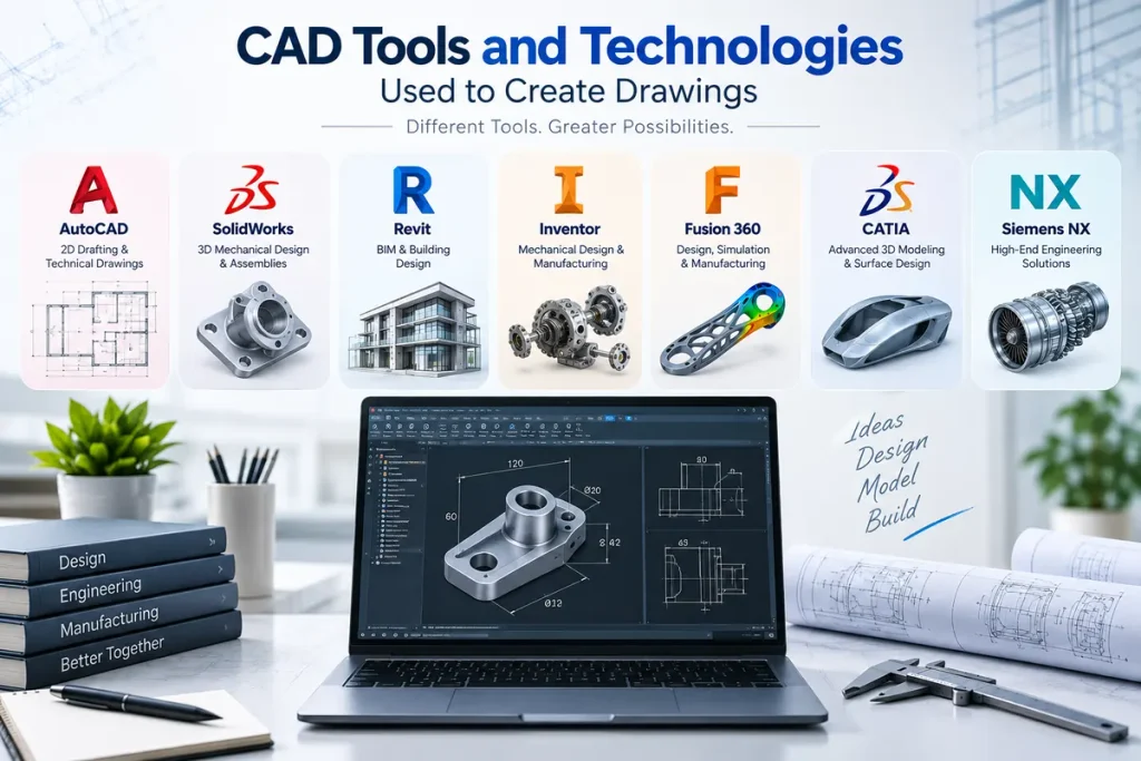
CAD Tools and Technologies Used to Create Drawings
Different CAD platforms support different drafting, modelling, documentation, and manufacturing requirements. The choice of software depends on the type of project, level of detail, industry, and intended use of the drawing.
AutoCAD
AutoCAD is commonly used for the design and creation of accurate 2D CAD drawings, including plans, elevations, sections, layouts, dimensions, and technical details. It is used in a wide range of industries, including architecture, engineering, construction, and manufacturing.
SolidWorks
SolidWorks is primarily used for 3D mechanical design, product modelling, assemblies, and engineering components. Its parametric modelling tools provide greater control over design dimensions and relationships, making it an effective solution for mechanical design services across a wide range of engineering and product development applications.
Revit
Revit is utilized for BIM-based building design, documentation, and management. It is designed to help architects and construction professionals create coordinated building models and generate plans, sections, elevations, schedules, and other project-specific drawings.
Autodesk Inventor
Autodesk Inventor is used for 3D mechanical design, assemblies, and engineering component design, as well as manufacturing documentation. It enables engineers to create detailed component models and generate manufacturing drawings from them.
Fusion 360
Fusion 360 is a 3D modelling and engineering software that combines simulation and manufacturing features. It is ideal for product design and development, making it a suitable solution for 3D modeling services while seamlessly connecting design and manufacturing processes, including CNC machining.
CATIA
CATIA is a software application used for 3D modelling and surface design, as well as assemblies and engineering. It is a powerful tool for complex product design and development in industries that require sophisticated engineering solutions.
Siemens NX
Siemens NX is a CAD software application that offers a comprehensive set of tools for advanced CAD modelling, engineering, design, simulation, and manufacturing.
SketchUp
SketchUp is a 3D modelling software that is widely used in the architectural industry, as well as for product design and development. It is a powerful tool for visualizing and communicating spatial ideas, as well as building and interior design concepts.
Rhino
Rhino is a 3D modelling software that is primarily used in architecture, industrial design, and other design fields that require complex modelling and surface design capabilities. It is a powerful tool for creating complex 3D models with great precision.
MicroStation
MicroStation is a 2D and 3D design software that is used in a wide range of industries, including architecture, engineering, construction, and infrastructure. It is a powerful tool for technical design and documentation, including large-scale projects.
Solid Edge
Solid Edge is 3D modelling and assembly design software that is used to design mechanical components, as well as to create engineering drawings.
Specialised CNC and Manufacturing Software
Specialised manufacturing software is often used in manufacturing engineering to transform CAD designs into CNC machining and fabrication drawings, cutting, machining, and other manufacturing processes.
How Design Information Becomes a CAD Drawing
Creating a CAD drawing involves more than transferring a sketch into digital format. The process moves from reviewing the available information to developing the drawing, adding technical details, checking the documentation, and preparing the final file for its intended use.
Step 1: Review the Project Information
The process begins by reviewing the design files, sketches, specifications, dimensions, drawings, materials, and project requirements. The drafting team goes through the technical and project standards related to the designs before they are drafted if it is engineering drawings.
Step 2: Define the Drawing Requirements
The drawing views, dimensions, scale, layers, annotations, standards, file format and level of detail are set according to how the drawing will be used. For example, CAD plans may have specific scales, dimensions, annotations and layout conventions according to the project.
Step 3: Develop the CAD Geometry
The approved design information is converted into accurate digital geometry using the appropriate CAD software. Lines, curves, shapes, components, or 3D models are developed according to the project requirements.
Step 4: Add Dimensions and Technical Details
Such elements include dimensions, tolerances, materials, annotations, symbols, notes, construction details, and so forth. All of these elements provide the drawing with the necessary technical information that is needed for the purpose of the particular drawing.
Step 5: Check and Coordinate the Drawing
The completed drawing is reviewed for dimensional accuracy, consistency, missing information, and drafting errors. It is also checked against related drawings and project requirements to identify potential coordination issues.
Step 6: Revise and Finalise
Any review comments or required changes are incorporated into the drawing. The latest approved information is then checked to ensure the final version reflects the required revisions.
Step 7: Issue the Final CAD Drawing
Once the drawing has been reviewed and all required revisions have been incorporated, the final CAD file is prepared and issued in the format required for its intended use. Depending on the project, it may be submitted for design approval or used for manufacturing, fabrication, construction, installation, or project records. The completed drawing is then incorporated into the relevant drawing set.
Types of CAD Drawings
Different projects need different documentation. Some of the types include:
2D CAD Drawings
A 2D computer-aided design (CAD) drawing uses length and width to depict objects on a flat plane. Plan, elevation, section, layout, and detail drawings are examples of this type of drawing.
3D CAD Drawings
3D CAD documentation represents objects with depth as well as height and width. It is useful for product development, mechanical components, furniture, complex assemblies, and visualising how parts fit together.
Technical CAD Drawings
The technical information contained in a CAD drawing is very specific to engineering, manufacturing, construction, or assembly. It usually contains information about dimension, tolerance, material, and many more.
Shop and Fabrication Drawings
Shop drawings give details that are essential for manufacturing or fabricating a particular component. Millwork, steelwork, furniture, mechanical parts, and architectural products often need shop drawings.
CAD Plans
CAD layout provides a view of a space, layout, system, or component from a defined direction. Architectural floor plans, furniture layouts, equipment layouts, and site plans are common examples.
What Makes a CAD Drawing Production-Ready?
Not every CAD drawing is ready for manufacturing or construction.
The design drawings ready for manufacturing should be able to address all the questions that the person who is making the part will ask. The questions include: What does the part measure? What materials are needed? How are the parts connected? Where are the fixing points? What are the tolerances? How is the part associated with other parts?
Before issuing a drawing, teams should check:
- Are all Critical Dimensions defined?
- Are materials and finishes specified?
- Are construction and connection details provided sufficiently?
- Do the related drawings contain identical data?
- Are all revisions recorded clearly?
- Does the drawing reflect the latest approved design?
- Is the file format appropriate for the following stages of the workflow?
These checks are often more important than simply producing the drawing quickly.
Curious about which format is better suited to your project? Know more about the key differences between 2D and 3D CAD Drawings.
Benefits of CAD Drawings for Businesses
Well-developed CAD documentation can provide practical advantages throughout a project.
- Higher accuracy: Digital drawing is more accurate for dimensions, geometry, and relationships among different parts.
- Increased speed: Modifications can be made without the need to draw everything all over again.
- Better teamwork: People can refer to one common document instead of trying to understand different sketches or ideas.
- Decreased probability of mistakes: There will be no room for error since everything is clearly defined.
- Improved documentation management: It will be easier to organize digital documents by drawing numbers, revisions, layers, etc.
- Scalability: Companies will be able to reuse CAD standards on various projects/products.
Common CAD Challenges and How to Overcome Them
| Challenge | Practical solution |
| Incomplete design information | Identify missing information before drafting begins |
| Frequent design changes | Use controlled revisions and maintain an updated drawing register |
| Inconsistent drawing standards | Establish templates, layers, naming conventions, and documentation standards |
| Coordination conflicts | Review CAD drawings against related architectural, structural, MEP, or manufacturing information |
| Limited internal drafting capacity | Use external CAD drafting support for additional project capacity |
| Poor legacy drawings | Redraw or convert outdated files into structured, editable CAD documentation |
CAD Drawing Examples: Which Industries Use Them?
CAD drawings are used across industries where products, spaces, components, or systems must be accurately defined.
- Architecture and construction: Floor plans, elevations, sections, details, and construction documentation.
- Manufacturing: Component drawings, assembly drawings, production details, and fabrication documentation.
- Millwork and furniture: Cabinet drawings, joinery details, furniture layouts, material schedules, and shop drawings.
- Mechanical engineering: Machine components, assemblies, sheet metal parts, and engineering drawings.
- Product development: 3D models, component drawings, prototypes, and manufacturing documentation.
- Interior design: Custom furniture, cabinetry, layouts, wall panelling, and detailed interior elements.
How Shalin Designs Supports CAD Drawing Requirements
Shalin Designs provides professional CAD drawing services for businesses that require accurate, detailed, and production-focused technical documentation. We work with project teams across the USA, UK, Canada, Australia, Singapore, Norway, Ireland, the UAE, and other parts of Europe, supporting different industries with project-specific drawing requirements.
Our services include 2D CAD drawings, 3D product modelling, engineering drawings, cad plans, millwork and shop drawings, furniture drawings, and manufacturing documentation. All drawings are produced according to their end-use application, project requirements, and level of detail needed resulting in effective documentation for Architects, Engineers, Manufacturers, Fabricators, and Contractors.
Final Takeaway
A CAD drawing is more than a digital version of a hand drawn plan, it is a structured technical document communicating the information required to design, manufacture, assemble, construct or install something correctly.
The value of a CAD drawing comes from the quality of the information it contains. Easy to read dimensions, appropriate views, material, construction and reference information along with revision control provide value throughout the lifecycle of a project or product.
For businesses which deal with complex products, custom millwork, engineering components or construction projects, the right CAD drafting workflow can help remove uncertainty before it results in an expensive production or site problem.