

Paying the price for design errors and constant rework? Investing in mechanical CAD drafting services can help improve accuracy, streamline production, and reduce these avoidable costs. Read on to know how.
A single missed tolerance. One unclear dimension. An annotation that two people on the shop floor interpret differently.
Any one of these small errors can derail an entire production run triggering expensive rework, wasted raw materials, missed delivery deadlines, and in some cases, complete component failure. If you’ve been in manufacturing long enough, you’ve seen it happen.
That’s exactly why investing in professional mechanical 2D drafting services isn’t just a smart operational choice, it’s a form of risk management. This guide breaks down what these services actually involve, where errors tend to creep in, and how precise technical drawings save your business far more than they cost.
What Are Mechanical 2D Drafting Services?
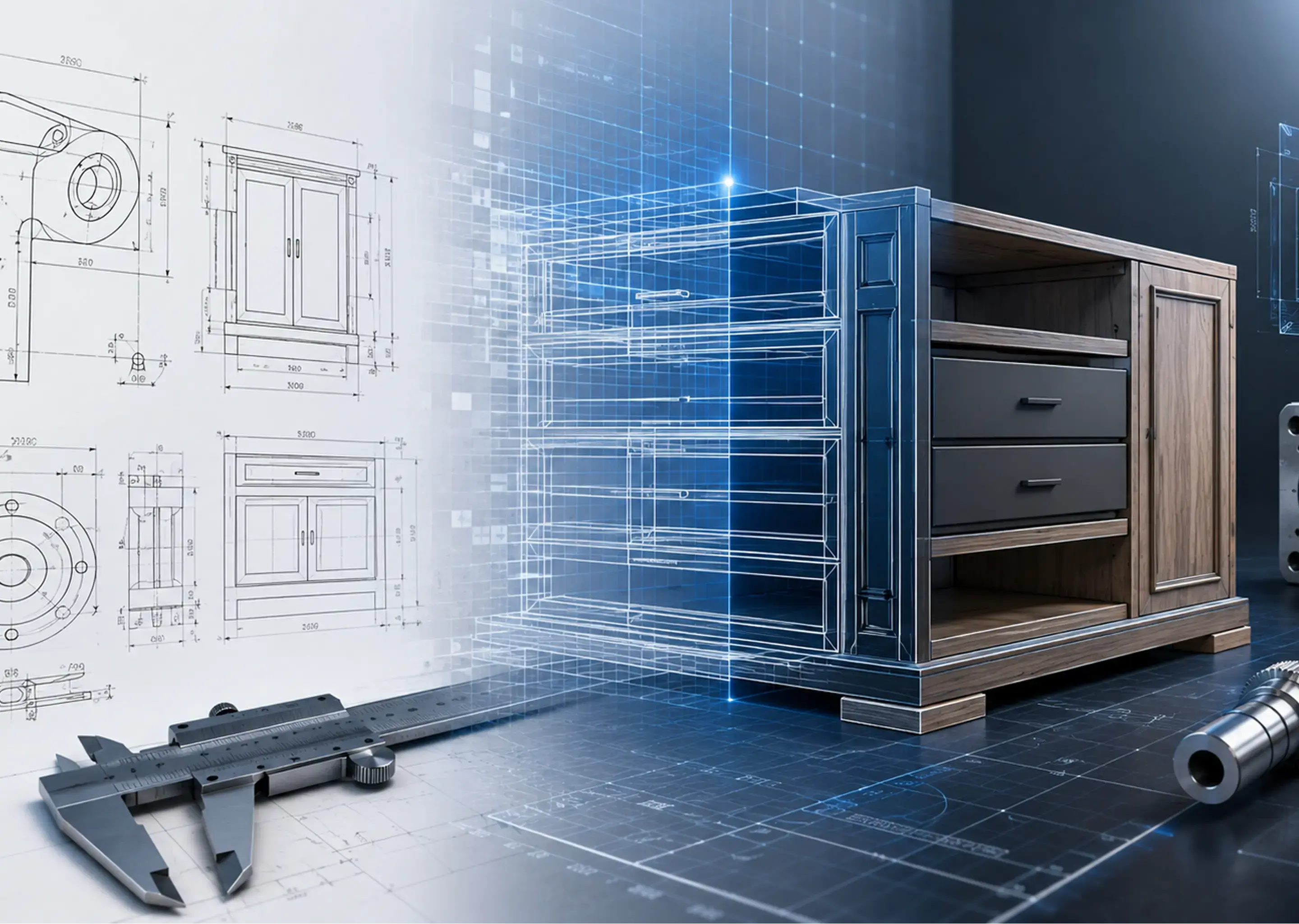
Mechanical 2D drafting is the process of creating precise, two-dimensional technical drawings that document every aspect of a mechanical component or assembly from its dimensions and material specifications to its surface finish requirements and geometric tolerances.
These drawings serve as the primary communication link between design engineers and the people actually building the part. A machinist, fabricator, or quality inspector should be able to pick up a well-drafted 2D drawing and know exactly what needs to be made, how it should be made, and how to verify it was made correctly.
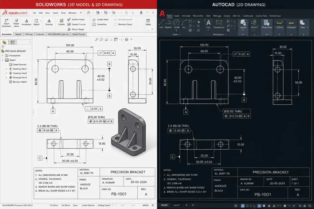
Modern mechanical drafting services use professional CAD software primarily AutoCAD and SolidWorks to produce drawings that are accurate, version-controlled, and easy to distribute across production teams, suppliers, and QC departments. The output is a production-ready blueprint, not a concept sketch.
Read Also: How Mechanical CAD Drafting Services Enhance Manufacturing
What a Complete 2D Drafting Package Includes
- Detail drawings for individual components with full dimensioning
- Assembly drawings showing how parts relate and fit together
- Bill of materials (BOM) with part numbers and material callouts
- Section views, exploded views, and detail callouts for complex geometry
- GD&T annotations specifying allowable geometric variation
- Surface finish symbols and fabrication/welding notes
The Real Cost of Inaccurate Mechanical Drawings
This is where most businesses underestimate the stakes.
Rework and material scrapping caused by drawing errors can cost anywhere from 5% to 20% of a project’s total budget. For a $500,000 production run, that’s up to $100,000 in avoidable losses — before accounting for idle labour, missed delivery windows, and damaged client relationships.
| Cost Category | Typical Impact |
| Material scrap from rejected parts | 2–8% of material cost per run |
| Rework labour (machining re-runs) | $80–$200/hr depending on process |
| QC re-inspection after corrections | Adds 1–3 days per batch |
| Delivery delays (client penalties) | Up to 5% of contract value |
| Total avoidable loss per project | 5–20% of total project budget |
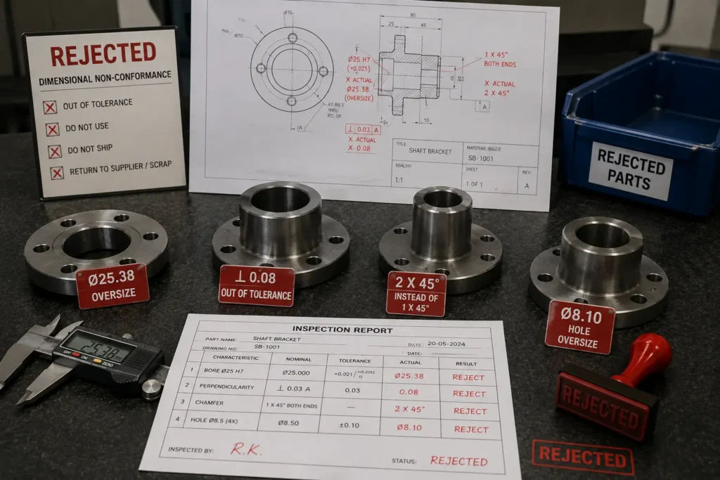
The errors themselves rarely look dramatic on paper. A misplaced decimal. A tolerance specified in the wrong unit. A material note referencing a grade that the supplier discontinued two years ago. Yet each of these oversights can cascade through a production chain in ways that are difficult and costly to rectify.
What Is GD&T and Why Does It Matter for Your Drawings?
GD&T stands for Geometric Dimensioning and Tolerancing. It’s a standardised engineering language governed by ASME Y14.5-2018 in North America and ISO 1101 internationally for communicating allowable variation in the geometry of manufactured parts.
Where traditional dimensioning tells you how big a feature should be, GD&T tells you how that feature needs to function. It answers questions like: Does this bore need to be perfectly perpendicular to the mating face? How much flatness deviation is acceptable before a sealing surface fails? How do position tolerances interact across an assembly?
Properly applied GD&T reduces manufacturing costs by 20–50% by eliminating interpretation disputes, reducing over-inspection, and preventing functional parts from being incorrectly rejected. (Source: ASME / SME research data)
Practical GD&T Example: Automotive Brake Caliper Housing
Consider a brake caliper housing where two threaded bores must align precisely with the mating bracket. A traditional drawing might specify ±0.2mm on X and Y individually which technically allows a part that’s 0.28mm off-axis (within tolerance diagonally) to fail assembly.
A GD&T-compliant drawing uses a True Position callout with a cylindrical tolerance zone, ensuring the bore is within 0.2mm of its true location in any direction. The part either works in assembly or it doesn’t guesswork, no disputes between the design team and the shop floor.
This is exactly why professional mechanical CAD drafting services must demonstrate real GD&T competency not just the ability to place callout symbols, but the engineering judgment to apply them correctly for the part’s functional requirements.
5 Tangible Benefits of Accurate Mechanical 2D Drafting
The cost of production is often higher for detailed mechanical items. Any minute changes in the design at the end moment can break down the entire chain of processes and cause delays. Such errors can cost a considerable amount of capital to the manufacturers. These errors are not only limited to financial losses. They can potentially tarnish the reputation of a business and damage future transactions.
Accurate fabrication drawing services help avoid these unnecessary costs and improve the ROI for any project, along with maintaining the brand reputation.
1. Faster Production With Fewer Interruptions
When the shop floor receives a clear, complete, and standards-compliant drawing, production flows. Machinists don’t stop to call the engineering team for clarification. QC inspectors work from a shared reference with no interpretive guesswork.
In a real-world machining environment, a single RFI (Request for Information) to engineering can cost half a day of production time. Eliminate the drawing ambiguity and you eliminate the RFI.
2. Measurable Cost Reduction Across the Project Lifecycle
The upfront investment in professional drafting pays back quickly. When you account for scrap rates, rework labour, rejected shipments, and project delays all of which trace back to drawing inaccuracies the economics of getting it right the first time are straightforward.
This is especially true for high-volume production, where a single drafting error gets multiplied across hundreds of components before quality control catches it.
3. Smoother Collaboration Across Teams and Suppliers
CAD-based drawings in standard formats (DWG, DXF, PDF) are easy to distribute, mark up, and track through revision cycles. When your design team, production team, QC department, and external suppliers all work from the same drawing revision with a clear history, miscommunication drops significantly.
4. A Valuable, Reusable Engineering Archive
Digital 2D drawings created in AutoCAD or SolidWorks can be archived, searched, and adapted for future projects. If you’re producing a new variant of an existing component, starting from a proven drawing baseline is far more efficient than starting from scratch and far less error-prone.
5. Scalability Without Compromising Quality
Professional drafting services scale with project size. Whether you’re running a five-piece prototype batch or preparing documentation for a 10,000-unit production order, the drawing standards stay consistent. Quality doesn’t erode as volume increases.
Read Also: What is CAD Design and Drafting Services and How It’s Useful?
How Is 2D Drafting Evolving In 2026?
The fundamentals of mechanical 2D drafting haven’t changed but the tools, standards, and expectations around those drawings are shifting in ways that matter for manufacturing businesses in 2026.
Model-Based Definition (MBD) Is Growing But 2D Isn’t Going Away
Model-Based Definition attaches GD&T, tolerances, and material specifications directly to the 3D CAD model eliminating the need for a separate 2D drawing in some workflows. Industries like aerospace and automotive Tier 1 suppliers are adopting MBD at a faster pace.
However, for the vast majority of manufacturers particularly SMEs, job shops, and companies working with suppliers in multiple regions the 2D drawing remains the standard. Most machine shops, fabricators, and CMM inspection systems still operate from 2D documentation. MBD is a complement to skilled 2D drafting, not a replacement.
AI-Assisted CAD Tools Are Changing Drafter Workflows
Tools like Autodesk’s AI drafting assistants and SolidWorks’ intelligent annotation features are reducing repetitive tasks for drafters auto-populating standard callouts, detecting missing dimensions, and flagging potential manufacturability issues. This makes skilled human drafters faster, not redundant.
The critical work interpreting design intent, applying GD&T correctly, understanding manufacturing constraints for the specific process still requires experienced engineering judgment that no current AI tool reliably provides.
Digital Thread and PLM Integration
In 2026, more manufacturers are connecting their 2D drawings directly to Product Lifecycle Management (PLM) systems like Siemens Teamcenter and PTC Windchill. This means drawings need to be created with metadata, revision control, and cross-system compatibility in mind from the start another reason why professional drafting services with PLM experience add more value than freelance drafters working in isolation.
The Drafting Services Market in 2026
The global drafting services market reached $5.98 billion in 2025 and is projected to grow to $6.24 billion in 2026 at a compound annual growth rate of 4.3%, according to The Business Research Company. This steady expansion reflects increasing demand for precision documentation across automotive, aerospace, industrial equipment, and electronics manufacturing sectors.
The growth is driven by manufacturers outsourcing non-core engineering functions to reduce overhead while maintaining access to specialised CAD expertise. For businesses in high-precision industries, the question is no longer whether to use professional drafting services, it’s how to select and manage the right partner.
How to Ensure Accuracy When Outsourcing 2D Drafting
Outsourcing mechanical drafting can be highly effective but it requires more than handing over a brief and waiting for results. Here’s what actually separates successful outsourcing relationships from frustrating ones.
Step 1 — Define Your Standards Before the Project Starts
Specify which drafting standards apply: ASME Y14.5-2018 for GD&T (North America), ISO 128 for drawing conventions, ISO 2768 for general tolerances. If your company has internal drawing templates or title block requirements, share them upfront not after the first deliverable comes back wrong.
Step 2 — Share Reference Drawings
Showing your drafting partner examples of drawings you consider high quality gives them a far clearer target than any written specification. Point out specific features how you want section views presented, how you prefer tolerance notes formatted, and what your title block must contain.
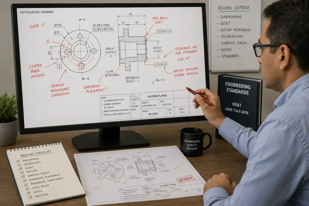
Step 3 — Build in a Structured Review Stage
A redline review where your engineering team marks up a draft drawing before it’s finalised catches errors before they reach the shop floor. This step is worth the time investment every single time. No drafting partner, however experienced, can fully anticipate every client-specific requirement without feedback.
Step 4 — Validate GD&T Competency Specifically
Many drafting services can produce clean-looking drawings with GD&T symbols placed on them. Fewer can correctly determine which GD&T controls are appropriate for a given functional requirement, or how to apply composite tolerances for pattern features. Validate this capability with a test drawing before committing a large scope of work.
Step 5 — Start With a Pilot Project
Before engaging a new drafting partner for a full project, run a small pilot two or three component drawings. Evaluate their accuracy, their responsiveness to feedback, their turnaround, and their ability to follow your standards. Scale up only after the pilot confirms they’re the right fit.
Which Industries Benefit Most From Professional Drafting Services?
Almost any industry that fabricates physical components benefits from precise 2D drafting but the stakes are highest where tolerances are tightest and production volumes are largest.
| Industry | Why Drafting Precision Is Critical |
| Automotive | High volumes amplify errors; complex assemblies with tight fits |
| Aerospace & Defence | Safety-critical parts; strict regulatory documentation |
| Industrial Equipment | Custom one-off fabrication; no margin for trial and error |
| Consumer Electronics | Miniaturisation; sub-millimetre tolerances in small housings |
| Shipbuilding & Marine | Long production timelines; late errors are extremely costly |
| Medical Devices | FDA compliance; traceability requirements on all dimensions |
2D Drafting vs. 3D CAD Modelling Do You Need Both?
This is one of the most common questions manufacturers ask, and the answer requires context.
2D mechanical drawings remain the standard for shop floor documentation, machining instructions, and quality inspection. They’re universally understood by fabricators, required by most procurement and QMS systems, and faster to produce for simpler components.
3D CAD models are better for design validation visualising complex assemblies, running interference checks, simulating loads, and generating prototypes. They’re increasingly used in the design phase before committing to production tooling.
For most manufacturing businesses, the two approaches work together rather than competing. The 3D model helps the design team confirm intent. The 2D drawing communicates that intent to the people making the part. Both serve different audiences with different needs.


